
AFPM Motor DFM: Pre-Tooling Evidence Review
Build a pre-tooling evidence dossier: screen assumptions, assign manufacturing review owners and export a DFM brief. Actual yield, retention capacity and tooling cost remain unknown.
Start DFM screening ↓Reviewed 2026-11-13 · Next review target 2027-05-13
DFM decision summary: what the screen can establish
Use the screen to prioritize review; use project evidence to release tooling.
Clearance is conditional
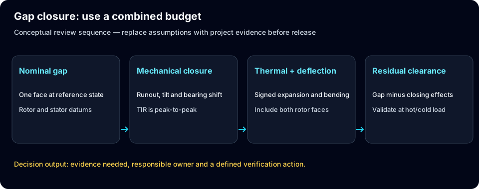
One-disc deflection and fixed tolerances omit coupled movement and hot dynamic loads.
Evidence and next action →Retention stays unknown
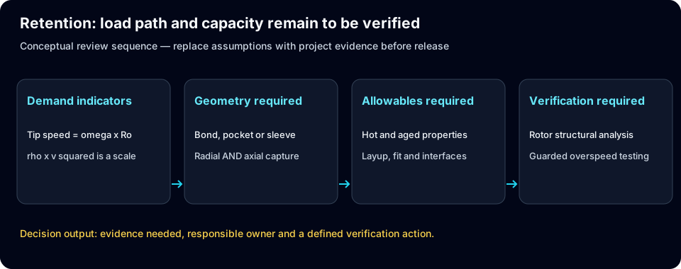
Tip speed and inertial stress do not establish bond, pocket or sleeve capacity.
Evidence and next action →Fill is a placeholder
Compare conductor area, resistance and temperature rise using declared denominators.
Evidence and next action →Balance needs a chosen grade
Grade and correction planes follow product requirements, not RPM alone.
Evidence and next action →Economics need accepted units
Obtain dated quotes and include scrap, inspection, tooling life and programme quantity.
Evidence and next action →Release needs evidence
Assign owners for qualified materials, guarded assembly and approved EOL criteria.
Evidence and next action →Target Audience & Applicability Boundary
- OEM engineering teams transitioning axial flux concepts to volume manufacturing
- NPI and manufacturing directors auditing supplier DFM readiness and tooling Capex
- Automotive EV traction, drone/eVTOL, and industrial direct-drive powertrain architects
- DIY hobbyists performing hand-glued rewinds without precision fixturing
- Final electromagnetic validation or safety certification
- Universal production sign-off without material lot qualification and overspeed testing
Production release dossier: 12 evidence actions
Follow supplier trials, mechanical evidence and release ownership in commissioning order. Each action needs a named owner and a project record before tooling approval. For derivations, use the mechanical DFM theory guide.
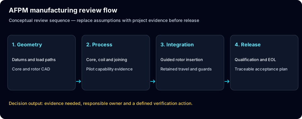
1. AFPM producibility: turn geometry into review gates
Start with the product duty, rotor/stator architecture and load paths. Thin axial packaging trades against disc stiffness, winding access and heat removal. The table is an editorial review plan, not measured factory capability. Prioritize unresolved interfaces before specifying automation.
- Suggested evidence owner
- Product engineering
- Record to obtain before release
- Drawing revision, duty and open-action register
| Interface | Decision evidence | Next action |
|---|---|---|
| Airgap | Datum drawings and hot loaded clearance | Allocate a stack for each gap |
| Core and coil | Loss, winding access and cooling trials | Compare candidate routes on the same duty |
| Assembly | Full force envelope and fixture fault analysis | Approve guarding and retained travel |
| Release | Pilot measurements and signed acceptance plan | Assign evidence owners |
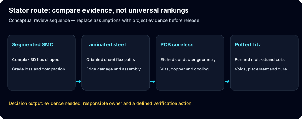
2. Core fabrication routes and supplier evidence
The Somaloy 5P product guidance specifies 600–800 MPa compaction and nitrogen heat treatment up to 650°C. These are grade-specific conditions, not instructions for all SMC materials. The route comparison below is qualitative; cost, cycle time, saturation and loss must come from a selected grade and supplier trial.
- Suggested evidence owner
- Core supplier
- Record to obtain before release
- Grade-specific process trial and die review
| Route | Manufacturing trade-off | Required trial |
|---|---|---|
| Segmented SMC | 3D shapes versus die, ejection and handling constraints | Grade-specific compaction, density and core loss |
| Tape-wound steel | Directional flux path versus slitting and assembly | Edge insulation, stack loss and dimensional checks |
| PCB coreless | Etched conductors versus vias and thermal limits | Current, resistance and temperature-rise test |
| Potted Litz | Formed coils versus placement and encapsulation effort | Void, cure and coil-position inspection |
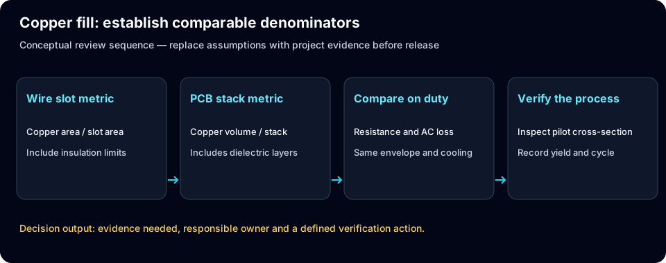
3. Winding fill: compare like-for-like denominators
The screen assigns fixed planning placeholders: SMC 54%, tape-wound 42%, PCB 24% and resin-Litz 46%. They do not respond to slot geometry and are not manufacturing ceilings. IPC current-capacity guidance concerns conductor size and temperature rise; it does not establish those fill values. Confirm resistance, insulation damage and hot-spot temperature on pilot parts.
- Suggested evidence owner
- Winding supplier
- Record to obtain before release
- Conductor and joint trial record
| Candidate | Access or process risk | Comparable evidence |
|---|---|---|
| Bobbin/flyer | Tooth edges, bend radius and enamel damage | Net copper area / declared window area |
| Needle/toroidal | Needle or shuttle clearance | Same denominator and insulation allowance |
| PCB | Copper thickness, vias and dielectric volume | Active conductor area, resistance and cooling |
| Formed bar / Litz | Joint quality, strand termination and placement | Joint tests and repeatable assembly samples |
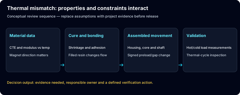
4. Potting and thermal mismatch: qualify the interface
The screen has a fixed thermal allowance, not a thermal network or resin model. Material expansion, modulus, cure shrinkage and constraints jointly determine movement and stress. The following is an editorial qualification checklist; the IEC reference supports the converter-fed insulation scope, not a universal resin CTE or filler recipe.
- Suggested evidence owner
- Materials / insulation owner
- Record to obtain before release
- Encapsulation qualification record
| Interface | Misuse risk | Mitigation |
|---|---|---|
| Coil to housing | Assuming CTE match eliminates stress | Use temperature-dependent properties and constraints |
| Magnet to disc | Using room-temperature adhesive strength | Test hot, aged bonds and representative cycles |
| Resin to PCB | Ignoring flow, cure exotherm and voids | Inspect representative potted assemblies |
5. Magnet containment: demand is not capacity
Tip speed is ωR and ρv² is an inertial stress scale, not the actual bond, pocket or sleeve stress. No universal speed band makes any retention method safe. For example, the June 2016 DP760 sheet reports overlap shear of 32 MPa at 23°C and 14.8 MPa at 120°C for FPL-etched 2024T3 aluminium cured seven days at 23°C. Those coupon results are not magnet-bond allowables; substrate, cure, ageing and loads differ. Capacity remains unknown for every tool result until geometry and qualified properties are supplied.
- Suggested evidence owner
- Rotor structural owner
- Record to obtain before release
- Hot/aged retention and overspeed evidence
| Concept | Unresolved load path | Verification action |
|---|---|---|
| Bond only | Hot aged shear and peel, bondline variation | Coupon qualification plus rotor analysis |
| Recessed pocket | Wall strength and axial capture | Check pocket geometry and contact loads |
| Metal ring | Fit, thermal expansion and axial escape | Check interfaces, losses and containment |
| CFRP sleeve | Layup, interference and conductive-fibre heating | Coupled structural and electromagnetic verification |
6. Reproducible tolerance budget: assumptions versus capability
Report reference preset (not the initial EV preset): 240 mm OD, Di/Do 0.58, 0.9 mm gap, 9 mm steel back-iron. Load the report reference preset to reproduce this table. Values below come directly from the screening engine. Mechanical allowances are unmeasured placeholder magnitudes; RSS carries no sigma or yield claim. Thermal closure is added linearly. TIR is not a ± allowance, and two-disc movement is not solved.
- Suggested evidence owner
- Mechanical design owner
- Record to obtain before release
- Measured per-gap clearance budget
| Contributor | Assumed magnitude (µm) | Interpretation |
|---|---|---|
| Rotor axial deviation | 24 | Not measured TIR |
| Bearing axial allowance | 30 | Replace with assembly evidence |
| Stator mounting allowance | 30 | Drawing-specific datums required |
| Magnet thickness allowance | 20 | Bondline variation also needs assessment |
| Directional thermal closure | 24 | Linear addition, not random variation |
| Mechanical RSS + thermal | 76.7 | Illustrative combined allowance |
| Linear worst-case stack | 128 | Excludes one-disc deflection |
| Remaining clearance proxy | 744.3 | 900 − one-disc deflection − worst-case stack; not validated minimum gap |
7. Bearing architecture: close the full load path
Do not add the displayed one-face force directly to external thrust. Opposing disc forces may balance globally while bending each disc; actual bearing reactions depend on architecture and asymmetry. No bearing arrangement, preload shim tolerance or fatigue life is selected by this screen. Obtain supplier calculations using the full duty, fits and thermal envelope.
- Suggested evidence owner
- Bearing / shaft designer
- Record to obtain before release
- Complete duty and reaction-load review
| Candidate arrangement | Decision question | Evidence still needed |
|---|---|---|
| Angular-contact pair | How are thrust and moments reacted? | Load spectrum, preload, fits and temperature |
| Crossed roller | Does the compact support meet stiffness needs? | Combined loads and seat geometry |
| Deep groove / compliant preload | Are thrust and stiffness sufficient for this duty? | Rated-life and displacement calculations |
8. Magnetic pull and controlled assembly
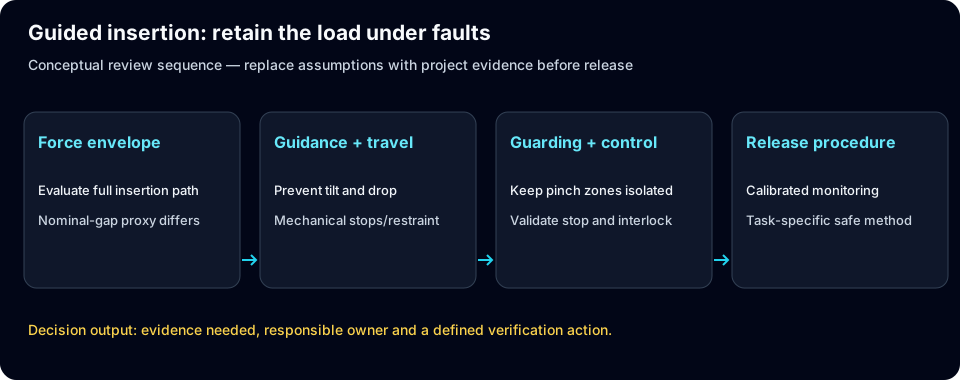
The tool uses uniform one-face pressure P = B²/(2μ₀) and force F = P·A. At assumed fields of 0.8 and 1.1 T this gives about 255 and 481 kPa; force also depends on the loaded area. Its magnetic circuit contains magnet thickness plus effective gap, so force is neither universally proportional to 1/g² nor exponential. This proxy is not an insertion-force rating or net bearing thrust.
- Suggested evidence owner
- Assembly tooling owner
- Record to obtain before release
- Guarded insertion-force and fault review
| Unknown | Why it matters | Evidence to obtain |
|---|---|---|
| Insertion path and tilt | Force changes through assembly travel | Geometry-specific force envelope |
| Pole coverage and saturation | Uniform annular loading is assumed | Calibrated magnetic analysis |
| Fixture load path | Nominal force omits faults and drops | Retained stops, guards and fault validation |
9. Balance provisions: a transparent numerical example
For a chosen illustrative grade G = 2.5 mm/s, e = 9549G/n in µm (equivalently g·mm/kg), and U = e·m in g·mm for mass m in kg. Values below are arithmetic examples for a 4.5 kg rotor, not mandatory AFPM grades. Grade, correction planes and rigid/flexible behaviour require project selection; balance does not correct face runout or remove all vibration.
- Suggested evidence owner
- Balance process owner
- Record to obtain before release
- Correction access and acceptance record
| Speed (RPM) | Assumed G (mm/s) | e (µm) | U for 4.5 kg (g·mm) |
|---|---|---|---|
| 1500 | 2.5 | 15.91 | 71.62 |
| 6000 | 2.5 | 3.98 | 17.90 |
| 12000 | 2.5 | 1.99 | 8.95 |
10. EOL access and acceptance criteria
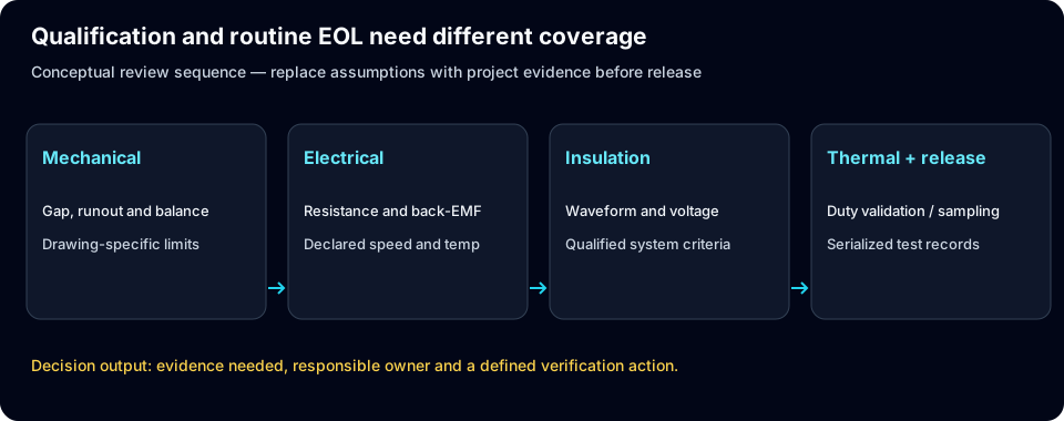
Separate insulation qualification, routine inspection and duty validation. IEC 60034-18-41 addresses Type I converter-fed insulation; its public scope is not a universal hi-pot or surge setpoint. An approved product test plan must state voltage, waveform, duration, temperature, uncertainty and acceptance criteria. EOL coverage does not guarantee zero defects.
- Suggested evidence owner
- Quality / test owner
- Record to obtain before release
- Serial-traceable test and disposition plan
| Station | DFM access provision | Acceptance evidence |
|---|---|---|
| Insulation | Safe insulated terminals and guarded contact fixture | Approved system-specific test specification |
| Resistance | Four-wire contact pads | Temperature-corrected product limits |
| Back-EMF | Repeatable drive coupling and sensor alignment | Declared speed and waveform limits |
| Gap and runout | Probe access at specified datum/radius | Loaded hot-clearance validation plus inspection plan |
11. Tooling economics: accepted units drive break-even
Mercedes-Benz reports 98 process steps in its June 2026 production announcement. That demonstrates one industrial implementation, not transferable cost savings or cycle times. For a local example only, an extra $20,000 fixed cost and $8 saving per accepted unit break even at 2,500 accepted units over the programme, not necessarily per year. Currency: illustrative USD as of this review, not a market quote. The interactive engine assigns route categories only.
- Suggested evidence owner
- Manufacturing / sourcing
- Record to obtain before release
- Dated fixed and accepted-unit cost quotes
| Cost term | Known here | Minimum sourcing action |
|---|---|---|
| Tooling and guarding | Unknown; no supplier quote | Request scope, ownership, life and maintenance |
| Variable cost | Unknown; no measured labour or scrap | Quote per accepted unit with inspection |
| Lifetime quantity | Annual input only; duration unknown | Confirm committed demand and ramp |
| Route comparison | Δfixed / Δunit saving if saving > 0 | Include financing, rework and downtime |
12. Design-freeze checklist: close unknowns before release
Use this proposed checklist to organize a project review. It is not a certification scheme or a standard-mandated set of numeric limits. A high screening score, single nominal clearance or an attractive capex estimate cannot replace approved drawings, qualification records and accountable release decisions.
- Suggested evidence owner
- Project release authority
- Record to obtain before release
- Signed evidence register before tooling
| Gate | Evidence required | Owner to assign |
|---|---|---|
| Clearance and structure | Signed hot/dynamic stack and geometry-specific structural analysis | Mechanical engineering |
| Magnet containment | Qualified material data, load paths and guarded validation plan | Rotor engineering |
| Winding and insulation | Pilot process capability and applicable qualification records | Electrical/process engineering |
| Assembly and EOL | Validated guarded process and serialized acceptance records | Manufacturing/quality |
| Commercial release | Dated quotes and accepted-unit economics | Programme sourcing |
13. Illustrative Engineering Scenarios: DFM Trade-Offs & Mitigation Pathways
Four illustrative presets calculated by the same engine as the tool. These are model examples with stated assumptions, not physical case studies, measured production results or application approvals.
EV High-Performance Traction Motor
Core DFM Challenge:
The tight gap and series-volume target couple rotor stiffness, hot containment and repeatable coil joining. Automation needs pilot capability evidence, not a high screening score.
Recommended verification actions:
- ▪Measure the hot loaded gap and validate both rotor supports.
- ▪Trial the coil joining and insulation process before ordering dedicated winding tooling.
- ▪Obtain geometry-specific retention analysis, hot/aged material data and a guarded overspeed test plan before release.
Reproducible model outputs and unknowns:
- ✓One-face force proxy 17.58 kN; plate deflection proxy 29.5 µm.
- ✓Remaining clearance proxy 636 µm; heuristic score 98/100 (Lower Modeled Concern — Unverified).
- ✓Retention capacity, actual yield, cost, bearing life and certification remain unknown. Load this preset above to reproduce the arithmetic.
eVTOL / Drone Coreless Propulsion
Core DFM Challenge:
The coreless preset prioritizes mass, but actual PCB thickness and cooling are absent from the magnetic proxy. Neither propulsion performance nor flightworthiness is established.
Recommended verification actions:
- ▪Replace the fixed effective-gap assumption with the real stator and rotor stack.
- ▪Compare PCB current capacity, hot-spot temperature and rotor containment at the declared duty.
- ▪Obtain geometry-specific retention analysis, hot/aged material data and a guarded overspeed test plan before release.
Reproducible model outputs and unknowns:
- ✓One-face force proxy 4.65 kN; plate deflection proxy 21.6 µm.
- ✓Remaining clearance proxy 1069.9 µm; heuristic score 98/100 (Lower Modeled Concern — Unverified).
- ✓Retention capacity, actual yield, cost, bearing life and certification remain unknown. Load this preset above to reproduce the arithmetic.
Industrial Direct-Drive Pump / Generator
Core DFM Challenge:
A larger low-speed disc still needs a full stiffness and thrust load-path assessment. External pump or generator loads and sealing requirements are outside the screen.
Recommended verification actions:
- ▪Separate opposing magnetic forces from external thrust in a complete free-body model.
- ▪Obtain bearing, environmental and seal qualification evidence for the actual application.
- ▪Obtain geometry-specific retention analysis, hot/aged material data and a guarded overspeed test plan before release.
Reproducible model outputs and unknowns:
- ✓One-face force proxy 32.45 kN; plate deflection proxy 24.2 µm.
- ✓Remaining clearance proxy 1302.3 µm; heuristic score 98/100 (Lower Modeled Concern — Unverified).
- ✓Retention capacity, actual yield, cost, bearing life and certification remain unknown. Load this preset above to reproduce the arithmetic.
High-Torque Robotic Hub Joint
Core DFM Challenge:
The AFIR resin-Litz preset combines a compact disc with high peak speed. The simplified one-face proxy does not solve the actual two-stator force balance or joint positioning accuracy.
Recommended verification actions:
- ▪Resolve the coupled AFIR load path and hot dynamic clearance with the actual geometry.
- ▪Validate potted coil placement, sensor alignment and the required actuator duty separately.
- ▪Obtain geometry-specific retention analysis, hot/aged material data and a guarded overspeed test plan before release.
Reproducible model outputs and unknowns:
- ✓One-face force proxy 2.91 kN; plate deflection proxy 3.1 µm.
- ✓Remaining clearance proxy 604.6 µm; heuristic score 98/100 (Lower Modeled Concern — Unverified).
- ✓Retention capacity, actual yield, cost, bearing life and certification remain unknown. Load this preset above to reproduce the arithmetic.
14. Physics Screening Engine Verification & Software Traceability
Model 2026.11.13-dfm-v3 uses deterministic arithmetic and explicit assumptions. Automated checks cover input rejection, scaling, tolerance budgets and unknown retention capacity. Software checks verify implementation behaviour; they do not validate physical accuracy. Reproduce the four examples with the named presets, inspect the method disclosure, then download the inputs, outputs and assumptions.
Return to presets and export the model record ↑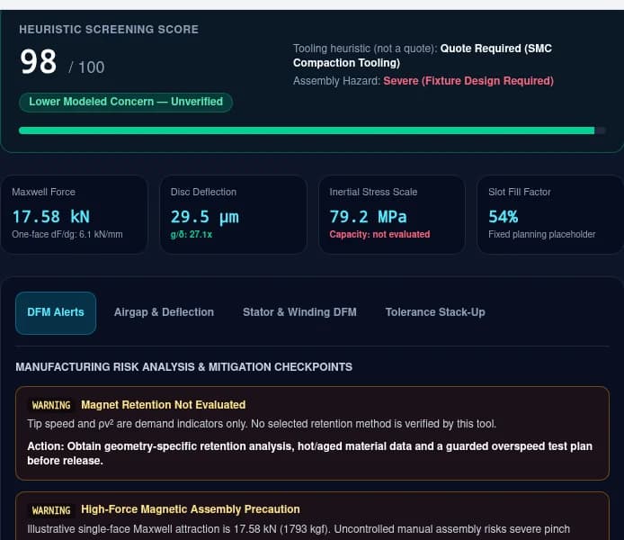
15. Frequently Asked Questions: AFPM Motor DFM
Practical answers to 20 critical engineering, tolerancing, tooling, and commercial sourcing questions across four categories.
Build a pre-tooling review record
Which preset should start an OEM DFM review?
Choose the closest declared architecture, then replace every input with drawing and duty values. Presets are reproducible examples, not validated products or recommended application designs.
Why is the report budget different from the initial EV screen?
The report explicitly uses the 240 mm reference input set, while the initial EV preset uses 260 mm. Load the report reference preset to reproduce 128 µm worst-case and 76.7 µm mechanical RSS plus thermal allowance. Neither is measured capability.
What does a DFM brief leave unresolved?
It records geometry, duty, heuristic outputs and assumptions. Attach CAD revision, datum scheme, hot operating limits, retention evidence, inspection plan and named approval owners; the export cannot release tooling.
What happens when a required numeric field is blank?
The tool removes its prior result and disables export until all required fields are valid. A blank value is not treated as zero or a reusable previous design.
How can a reviewer reproduce a changed screening record?
Download Engineering JSON with inputs, outputs, model version and assumptions, identify the drawing revision separately, then enter the same values. The evidence screenshot records one EV preset run, not every custom design.
Commission manufacturing trials
What should an SMC supplier return before die release?
Request the selected powder grade and process sheet, compaction and heat-treatment route, die/ejection review, density and loss measurements, dimensional trial results and an itemised tooling quote. A material-family web page cannot close these actions.
Which coil trial evidence belongs in the dossier?
Use the actual conductor and enamel system. Record the conductor-area denominator, resistance, joint damage checks, thermal rise, winding access, trial quantity and rejected parts before choosing an automation route.
Does the topology selector establish a valid magnetic circuit?
No. Topology and pole/slot counts primarily record RFQ context; only limited compatibility is checked. The common one-face proxy does not solve topology-specific flux return, net bearing thrust or winding feasibility.
Does a coreless preset include the actual winding-disc thickness?
No. It substitutes an illustrative 1.8 times mechanical gap and does not accept stator thickness. Its field, force and deflection outputs cannot predict a real coreless design without a geometry-specific magnetic and structural model.
Does a winding route label prove automation is available?
No. It describes a candidate process category, not a supplier capability or quoted cycle time. Obtain trial evidence, access constraints and a scoped machine/fixture quote for the project volume.
Assign verification owners
Who closes the clearance evidence action?
The mechanical design owner combines drawing datums, measured hot/cold deviations, bearing movement and loaded structural analysis for each gap. The report reference arithmetic only shows how the assumed budget is assembled.
Can a copied score close a magnet retention action?
No. Retention capacity is not evaluated. Assign an owner for qualified hot/aged material data, radial and axial load paths, detailed geometry and the project overspeed validation plan.
What record distinguishes assembly review from running-duty review?
Use a separate assembly force-versus-travel and fault/guarding assessment. The nominal operating-gap one-face force is not a fixture rating, net bearing load or permission for manual assembly.
What must be specified before ordering a balance fixture?
Define rigid/flexible behaviour, the project-selected balance grade, service speed, correction planes, accessible correction features and the measurement method. The numerical example is not a universal G2.5 requirement.
Which EOL details need agreement with the winding supplier?
Agree test allocation, converter waveform, temperature, acceptance limits, instruments, calibration, serial traceability and failed-unit disposition. Public IEC scope alone does not supply universal hi-pot or surge limits.
Approve tooling and cost assumptions
How is accepted-unit tooling break-even calculated?
Divide additional fixed cost by the quoted saving per accepted unit across the programme horizon. The illustrative USD 20,000 divided by USD 8 equals 2,500 accepted units; it is not a market quote or annual-volume threshold.
Can low prototype volume remove an SMC die requirement?
No. A pressed SMC route still requires appropriate compaction tooling. Ask whether existing tooling, a prototype route or a new dedicated die is proposed, and quote its ownership and replacement terms.
What evidence closes a potting-process action?
Record resin grade, cure and exotherm, void inspection, insulation checks, adhesion and representative thermal/environmental cycling. Select vacuum casting, encapsulation or impregnation from those requirements; VPI is not universally mandatory.
Does the screenshot demonstrate supplier production yield?
No. It is a real software execution capture with a provenance hash, inputs and unknown retention status. Supplier yield, physical performance and customer approval require separate permissioned records.
When should the pre-tooling dossier be reviewed again?
Reopen affected actions after CAD, material, supplier, process, duty or acceptance-limit changes. This page targets a source/model review by 2027-05-13; that date is not a project qualification interval.
16. Technical References & Evidence Sources
Published · Reviewed · Next review . Published by AFPM Motor. Referenced standards and peer-reviewed literature:
- Gieras, Wang & Kamper — Axial Flux Permanent Magnet Brushless Machines ↗
Springer, second edition, 2008; publisher record checked 2026-11-13
Background on AFPM analysis, construction and applications. The public record does not validate our uncalibrated plate coefficient, heuristic score or manufacturing capability.
- Mercedes-Benz — Large-scale production of electric axial flux motor ↗
Manufacturer announcement, 2026-06-09; checked 2026-11-13
Reports production start in Berlin-Marienfelde, 98 process steps and around 30,000 m² of production space. Evidence of one industrial programme, not a site audit or proof of our cycle times, costs or yield.
- Höganäs — Somaloy 5P ↗
Manufacturer product guidance; checked 2026-11-13
For the 5P family: 600–800 MPa compaction with heated/controlled tooling and nitrogen heat treatment up to 650°C. Other grades require their own process sheet; no universal die geometry or tooling price is established.
- 3M — Scotch-Weld Epoxy Adhesive DP760 product data sheet ↗
Manufacturer technical data, June 2016; checked 2026-11-13
Temperature-dependent performance depends on substrate preparation, cure and test conditions. Temperature resistance is not a continuous-service magnet-retention allowable. Qualify the actual hot, aged bondline.
- ISO 21940-11:2016 — Balancing rotors with rigid behaviour ↗
ISO, 2016; Amendment 1:2022; catalogue checked 2026-11-13
Covers residual-unbalance tolerances, correction planes and allocation for rigid rotors. Does not cover flexible rotors or impose one AFPM balance grade based on RPM alone.
- IEC 60034-18-41:2014+AMD1:2019 — Type I converter-fed insulation systems ↗
IEC consolidated edition 1.1, 2019, with 2020 corrigendum; checked 2026-11-13
Qualification and quality-control framework for Type I PWM converter-fed winding insulation. The public scope does not establish a universal hi-pot, surge, leakage or back-EMF threshold.
- ASME Y14.5-2018 (R2024) — Dimensioning and Tolerancing ↗
ASME catalogue and scope; checked 2026-11-13
Drawing language for GD&T and datum references. Datum letters and allowable runout must be chosen for the actual assembly; this is not a source for our placeholder tolerances.
- IPC-2152 — Printed-board current-carrying capacity, public scope ↗
IPC public standard excerpt; checked 2026-11-13
Relates conductor dimensions, current and acceptable temperature rise. Does not prescribe a universal PCB-motor copper fill percentage, efficiency or production yield.
Request an OEM DFM Tooling & Producibility Review
Transitioning an axial flux motor design from simulation to repeatable series production requires disciplined mechanical tolerancing, structural disc stiffness validation, and magnetic assembly tooling. Export your DFM brief from the calculator above or send your 3D CAD step files and duty specifications to our manufacturing engineering team.
Inquiry Email
Please include application, peak/continuous torque, speed range, voltage/current limit, outer diameter, axial length, cooling method, quantity, and drawings or reference samples.
Instant Chat
WhatsApp Engineering Support
Share torque-speed, package, cooling, and sample quantity in the first message.