
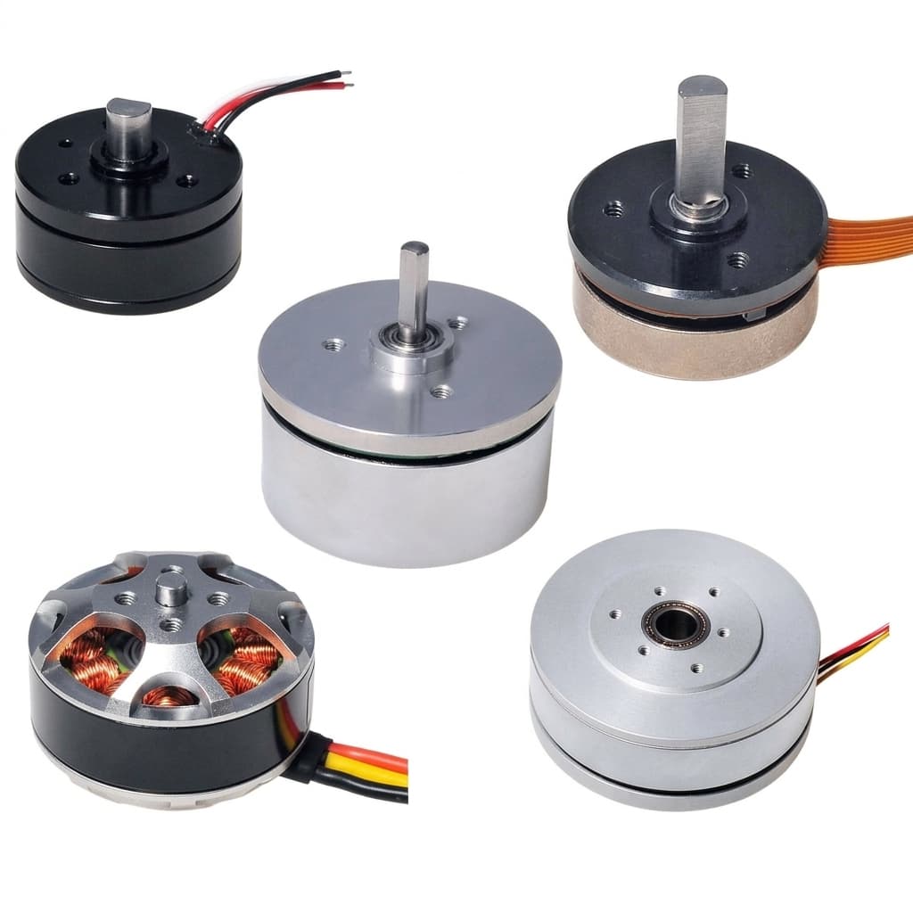
Air Gap Tolerancing and Dynamic Deflection in AFPM Motors: Thermal Stack, Housing Stiffness, and Factory Shimming Protocols
Review AFPM motor air gap tolerancing, thermal stack and rotor deflection with a worked clearance budget, factory shimming workflow and supplier RFQ checklist.
Executive Summary for Procurement & Powertrain Engineering: AFPM motor air gap tolerancing must account for the minimum running clearance, rather than just the nominal dimension on a drawing. Rotor face runout, housing compliance, differential thermal expansion and bearing movement can consume the same clearance budget. Magnetic attraction can amplify a closing displacement. Specify each gap's operating envelope, measure the assembly datums, select traceable shims and validate the hot, loaded structure before releasing a motor program.
Editorial review: 13 November 2026. Scope: global OEM mechanical design and sourcing of axial flux permanent magnet motors. The worked example uses an assumed 260 mm diameter, 75 kW machine; it is a reproducible engineering worksheet, not a measured production result or a supplier qualification. Its dimensions, material coefficients and acceptance targets are illustrative. Iron-cored and coreless machines have different magnetic circuits and force paths; do not transfer one topology's force model to another. Program-specific electromagnetic/structural finite element analysis (FEA), bearing models and tests remain necessary.
For initial sizing, review the AFPM Bearing Selection Guide & Calculator and AFPM Motor Design for Manufacturing Evaluator. If a drawing is already available, request an air gap tolerance review with the datum scheme, duty cycle and material stack.
1. The Physics of the AFPM Air Gap: Maxwell Stress and Negative Stiffness
In an ideal centered radial-flux machine, distributed radial forces can cancel at the shaft. An axial-flux machine instead exposes broad annular faces to normal magnetic loading. Even if opposing forces cancel at the assembly level, each rotor disc and its attachment must carry its local load.
For a predominantly normal field with negligible tangential contribution, a useful first estimate is:
F_ax ≈ B_n,rms² × A_active / (2μ₀)
Here, B_n,rms is the spatial root-mean-square normal flux density over one active face, in tesla; A_active = π(R_outer² − R_inner²) is that face's active area in square metres; and μ₀ ≈ 4π × 10⁻⁷ H/m. A sinusoidal spatial peak value must be divided by the square root of two before using this approximation. Substituting the peak directly would double the estimated force. For nonuniform fields and significant tangential flux, integrate the Maxwell stress over the actual surface using electromagnetic FEA.
For an assumed active area of 0.035 m² and spatial RMS normal flux density of approximately 0.734 T, the estimate is about 7,500 N on one face. This arithmetic illustrates a load scale; it is not a universal AFPM force rating.
The Clamping Feedback Loop (Negative Magnetic Stiffness)
Attraction generally rises as a gap closes. With force defined positive toward closure and gap length positive toward opening, the force-versus-gap derivative is negative: K_mag = dF_ax/dg < 0. The Soong et al. study on axial force negative stiffness examines this behavior, including double-sided arrangements and tilt.
A transparent single-face sensitivity example is F(g) = F₀ × [(g₀ + l_eq)/(g + l_eq)]², where l_eq represents an assumed equivalent magnetic length. Set F₀ = 7,500 N, g₀ = 1.00 mm and l_eq = 4.00 mm. Then:
- At 0.80 mm, the estimated attraction is 8,138 N, about 8.5% higher.
- At 1.20 mm, it is 6,934 N, about 7.5% lower.
- Changing the equivalent magnetic length changes these sensitivities. A physical-gap-only inverse-square law cannot be applied indiscriminately to permanent magnet machines.
This example treats a single face and neglects leakage and saturation. Shared flux paths in dual-rotor machines require a coupled model; the two calculated forces cannot simply be subtracted to predict a real assembly's bearing thrust. Check the actual shaft, rotor, stator and housing load paths.
For a simple translational mode, local static stability requires the mechanical restoring stiffness to exceed the magnetic closing stiffness in that same mode. A threefold ratio can be a project design margin, but it is not a universal stability standard. Tilt modes, resonances, thermal preload changes and peak external loads require separate assessment.
2. Dynamic Air Gap Budget Equation: From Static Drawing to Real Road Conditions
A drawing that specifies only 1.00 ± 0.10 mm at 20°C leaves the operating clearance undefined. Evaluate each side and the minimum clearance across radius, circumferential position, rotor angle and operating state.
A conservative five-component worksheet is:
g_dynamic-min = g₀ − (δ_mach + δ_thermal + δ_deflect + δ_bearing + δ_centrifugal)
- Nominal gap, g₀: Specify one physical clearance per side, excluding the stator or magnet thickness. State whether the reference is an unloaded CAD dimension or an assembled, magnetically loaded measurement.
- Machining and assembly loss, δ_mach: Include dimensional stack errors, face runout, potting variation and adhesive bond-line variation. Do not add the same geometry once as a tolerance and again as measured runout.
- Thermal closing loss, δ_thermal: Calculate signed growth of the actual datum paths using each part's temperature. Housing growth can open one gap and close another; hot windings do not establish the housing or shaft temperature.
- Structural closing loss, δ_deflect: Include rotor coning, stator movement, end-shield compliance and external loads. If g₀ is measured after magnetic engagement, subtract only additional operating deflection beyond that state.
- Bearing movement, δ_bearing: Include the applicable free play and loaded contact movement at the operating preload. Avoid counting the same bearing clearance in the machining allowance.
- Speed-related closing loss, δ_centrifugal: Obtain it from the geometry and constraints at maximum speed. A perfectly symmetric disc does not automatically dish merely because it expands radially; offsets, material gradients or constraints can create axial movement.
The five losses are worst-closing allowances for a defined load case. Do not sum unrelated maxima and call them a measured operating condition. Conversely, root-sum-square statistics cannot replace deterministic checks of thermal growth or magnetic deformation. Reserve a separate allowance for measurement uncertainty and the agreed acceptance guard band.
Figure 1: Cross-Sectional Force Balance, Thermal Stack Paths, and Factory Shimming Planes in a Dual-Rotor AFPM Motor
The schematic is not to scale. It identifies candidate adjustment planes, not a fully constrained bearing design. A shim that shifts a bearing can change preload as well as the gap; it cannot compensate for inadequate disc stiffness or an unvalidated thermal stack. Scroll the diagram horizontally on narrow screens to read its labels.
3. Cumulative Tolerance Stack-Up: The 8-Point Engineering Matrix
The following matrix is an illustrative allocation, not a machining capability claim. It assumes a nominal single-side gap of g₀ = 1.05 mm at 20°C before the listed losses. Use worst-case arithmetic for the initial interference screen; apply a statistical yield model only after establishing distributions, correlations and process capability.
Use ISO 1101:2017's geometrical specification framework to communicate form, orientation and runout controls. The standard does not prescribe the AFPM tolerances shown here. Identify the bearing datum axis, inspected radius and assembly condition on the drawing.
| # | Mechanical interface or feature | Assumed closing allowance (mm) | Budget term | Evidence needed for release |
|---|---|---|---|---|
| 1 | Housing stator-flange datum depth | 0.030 | Machining | Shoulder depth and datum orientation inspection |
| 2 | Stator potting and winding-face envelope | 0.040 | Machining | Face map across the active annulus after cure |
| 3 | Rotor back-iron face geometry | 0.025 | Machining | Flatness and assembled face runout, without duplicate allocation |
| 4 | Permanent magnet thickness variation | 0.020 | Machining | Segment thickness records and installed face envelope |
| 5 | Magnet adhesive bond-line variation | 0.025 | Machining | Fixture-stop verification and cured bond-line checks |
| 6 | Bearing-carrier shoulder location | 0.025 | Machining | Axial datum stack report after final fastening |
| 7 | Bearing free play plus additional contact movement | 0.035 | Bearing | Supplier load/preload model at the operating temperatures |
| 8 | Additional electromagnetic and mechanical disc bowing | 0.120 | Structural | Coupled FEA and deflection measurement at the critical radius |
Tolerance Synthesis & Margin Analysis
Rows 1–6 sum to δ_mach = 0.030 + 0.040 + 0.025 + 0.020 + 0.025 + 0.025 = 0.165 mm. Row 7 is counted once as δ_bearing = 0.035 mm; row 8 gives δ_deflect = 0.120 mm.
For a simplified thermal sensitivity, assume two effective 120 mm paths rise uniformly from 20°C to 120°C. Use illustrative coefficients of 23.4 ppm/K for aluminum and 11.5 ppm/K for steel. Their relative growth is:
ΔL = 120 × (23.4 − 11.5) × 10⁻⁶ × 100 = 0.1428 mm
Assign that full amount to gap closure only if the locating-bearing arrangement and datum directions justify it. Otherwise compute each path and each gap separately. Resin swelling, adhesive creep and nonuniform temperatures need their own evidence; they are not established by this two-material calculation.
Assume a further speed-related closure allowance of δ_centrifugal = 0.020 mm, pending validation. The total is:
Σδ = 0.165 + 0.1428 + 0.120 + 0.035 + 0.020 = 0.4828 mm
g_dynamic-min = 1.05 − 0.4828 = 0.5672 mm
The remaining clearance is 0.5672 mm. Against an example acceptance floor of 0.50 mm, the margin is only 0.0672 mm. With an assumed 0.010 mm measurement-uncertainty allowance, the guarded margin becomes 0.0572 mm. Those are different quantities: remaining clearance is not the same as margin above the release floor.
If the magnet allowance grows from 0.020 to 0.080 mm, another 0.060 mm is consumed. The guarded gap becomes 0.4972 mm, below the example 0.50 mm requirement. This is a release failure under those assumptions, not proof that physical rubbing has already occurred. The useful sourcing response is to tighten the relevant process, revise the nominal gap or redesign the compliant structure, then validate the changed stack.
For a program-specific allocation, use the DFM evaluator's manufacturing and release checklist before issuing a production RFQ.
4. Housing & Rotor Disc Structural Stiffness: Preventing Conical Dishing
A rotor disc attached at its hub can bend under magnetic loading on the surrounding annulus. Its behavior depends on hub clamping, outer-edge restraint, magnet attachment, ribs and material properties. Housing compliance must be included in the same clearance model rather than assumed rigid.
For a small-deflection, isotropic plate approximation:
D_flex = E × t_disc³ / [12 × (1 − ν²)]
w_max = k_c × F_ax × R_o² / D_flex
Use consistent SI units: Young's modulus E in pascals, thickness t_disc and radius R_o in metres, and force in newtons; the resulting deflection is in metres. The coefficient k_c depends on radius ratio, boundary conditions and the pressure distribution. Without that coefficient or a validated numerical model, this expression supplies a sensitivity, not an absolute deflection prediction. Laminated or composite structures require suitable directional stiffness properties.
Why Lightweighting Can Destroy Air Gap Control
With geometry, material and applied load otherwise unchanged, halving a solid plate's thickness from 12 mm to 6 mm reduces flexural rigidity to one eighth. An assumed initial deflection of 0.035 mm would therefore scale to 0.280 mm in this linear model. In a real magnetic circuit, force changes as the gap changes, so a coupled solution is needed as closure becomes significant.
Procurement action: request rotor and housing displacement maps under the maximum calculated magnetic force, external thrust, temperature distribution and speed. Include no-load, overload and fault states relevant to the program. A torque percentage alone does not define axial force: permanent magnets attract at zero torque, and current angle, saturation and topology affect the loaded force. Agree a deflection allocation from the clearance budget rather than imposing a universal percentage of nominal gap.
5. Factory Shimming Protocols & Assembly Metrology
Selective shimming can absorb measured assembly variation without requiring every component to hold the complete gap tolerance. Its economic advantage depends on actual machining capability, inspection time, automation and volume; no fixed scrap percentage or annual-volume threshold follows from the geometry alone.
Staged Assembly Workflow
- Inspect incoming components: measure rotor and stator faces, magnet envelopes and housing datums with calibrated equipment. Record the temperature and measurement uncertainty.
- Establish the datum stack: measure flange-to-face heights and bearing shoulder positions after the specified assembly operations. Identify which gaps each shim plane changes.
- Calculate the adjustment: for an adjustment plane that opens the gap when shim thickness increases,
Δt_shim = (g_target − g_measured)/s, where s is the measured or modeled gap change per unit shim thickness. The familiar unit ratio applies only when s equals one. Check both gaps and bearing preload before selecting a pack. - Install and record the shim pack: use qualified, burr-free shims with measured thickness. Candidate increments such as 0.025 or 0.050 mm must suit the acceptance band and measurement capability.
- Engage the magnetic assembly in controlled tooling: size the fixture and restraint for the verified force-versus-travel envelope. Keep fingers and loose gauges outside the closing load path.
- Verify the gap map: inspect both faces at multiple angular positions and radii where accessible. Four positions are an initial screen; they cannot establish that no local high spot exists between them.
- Apply final fastening and repeat the map: record torque sequence, bearing preload and serial number. Final tightening can change the gap and must precede the acceptance measurement.
- Run the qualified spin check: follow the guarded test procedure, beginning at the approved low speed. Use validated limits for runout, drag, vibration and temperature; prototype hot-load and overspeed qualification remain separate from routine EOL screening.
Shim Pack Specifications
Choose the shim material for clamp load, temperature, corrosion environment and magnetic compatibility. AISI 304/316, spring stainless and qualified laminated shims are candidate options, not interchangeable specifications. DIN 1.4310 is a spring-stainless grade, not brass; cold-worked stainless can also become magnetic. Specify the actual alloy, condition and permeability requirement where relevant.
Set thickness, parallelism and burr limits from the available gap budget. A 0.005 mm burr cap may be a drawing requirement, but the process must demonstrate it rather than assume all stamped or ground parts comply. Qualify peelable shim compression, layer integrity and thickness retention under the actual clamping load and temperature. Confirm that changing the pack does not overload the bearings. SKF's bearing execution guidance distinguishes initial, mounted and operating clearance and explains why fits and temperature affect preload.
In-Situ Metrology: Feeler Gauges vs. Non-Contact Sensors
This comparison describes method selection. Resolution is not installed accuracy; request calibration uncertainty, target-specific performance and measurement-system analysis before assigning acceptance limits. Equipment prices and capabilities depend on the supplier and installation.
| Measurement method | Useful measurement | Main limitation | Required qualification | Suitable stage |
|---|---|---|---|---|
| Non-magnetic feeler gauge | Accessible local static clearance | Access, contact feel, surface damage and pinch risk | Safe retained access and operator repeatability | Open prototype or approved in-process check |
| Capacitive gap probe | Non-contact displacement to a suitable target | Dielectric layers, grounding, target geometry and probe thickness | Calibrate against the actual conductive/coated surface | Instrumented subassembly or pilot fixture |
| Eddy-current probe | Displacement to conductive targets | Conductivity, permeability, temperature and nearby fields affect response | Calibrate to the actual ferrous or non-ferrous target | Instrumented rotor or housing checks |
| Laser triangulation | Accessible face position or runout | Line of sight, reflectivity, speckle and alignment | Surface-specific optical and motion validation | Open-frame subassembly inspection |
| Dial indicator | External face or shaft runout | Contact force and datum access; not a sealed internal gap measurement | Fixture rigidity and calibrated measurement radius | Incoming inspection and assembly datums |
| CMM or multi-probe height fixture | Component stack and face map | Measures accessible datums rather than an operating sealed gap | Temperature control, datum repeatability and stack correlation | Pre-closure dimensional gate |
6. Sourcing & RFQ Engineering Checklist: 10 Air Gap Quality Gates
Use the following as a supplier evidence request. Acceptance values must be approved for the particular topology and duty cycle; the numerical example above is not an industry standard.
- 1. Minimum dynamic gap: define both physical gaps, the reference assembly state, the operating envelope and the guarded minimum clearance. A 0.50 mm floor is only the worked example's target.
- 2. Datum and orientation controls: identify the bearing axis and stator mounting references, using an agreed geometrical tolerancing convention and inspection method.
- 3. Face runout: specify the inspected radius, rotational speed, loaded state and total indicated reading (TIR) limit. Explain whether the budget already includes that measured face envelope.
- 4. Magnet thickness and position: require segment and installed-face inspection records; use sorting bins only where the budget and process capability justify them.
- 5. Bond-line control: define adhesive, cure, fixture stops and verification of thickness and thermal stability.
- 6. Traceable shimming: retain the measured datum stack, adjustment calculation and selected pack against each assembly serial number.
- 7. Shim quality: agree alloy, condition, actual thickness, burr/parallelism limits and compression qualification at the intended clamp load.
- 8. Thermal stack: obtain signed expansion paths and component temperatures for cold soak, steady duty and transients, including the locating/floating bearing arrangement.
- 9. Structural release: request coupled magnetic and mechanical force/displacement results, boundary conditions, mesh/convergence evidence and correlation to prototype measurements.
- 10. EOL correlation: link accessible dimensional checks and electrical/mechanical screens to prototype gap measurements. Define reaction plans, sampling, uncertainty and the evidence needed to release a failed or reworked unit.
7. Frequently Asked Questions (FAQ)
Why does air gap control matter in axial flux motors?
The planar active area can generate substantial normal force and bending of the rotor or stator supports. Equal opposing loads may reduce net external thrust while leaving large internal loads. Radial-flux machines also need eccentricity and stiffness control; topology alone cannot establish which design has the tighter manufacturing requirement. In either case, check the operating clearance rather than only a cold nominal dimension.
How does thermal expansion affect the air gap in aluminum vs. steel housings?
It depends on the datum paths and component temperatures. In the worked example, equal 120 mm aluminum and steel paths heated by 100 K have 0.1428 mm of differential growth. Whether that closes or opens a particular gap depends on bearing location and rotor/stator restraint. With asymmetric temperatures, calculate each path separately and verify preload, both gaps and transient conditions. Changing housing material is a stiffness, mass, cooling and manufacturing tradeoff as well as a thermal one.
What is the typical nominal air gap for an industrial AFPM motor?
There is no single gap established by the AFPM label or power rating. This article uses 1.05 mm per side as an illustrative starting point. Select the actual value from magnetic performance, rotor diameter, face envelope, thermal movement, structural deflection, bearing stiffness, retention details and the required contamination allowance. For a coreless stator, also distinguish the two physical clearances from the total magnetic separation through the nonmagnetic stator.
Can we eliminate shimming by using high-precision CNC machining alone?
Sometimes. Compare measured process capability and total cost for fixed machining, selective component matching and shimming. Potting, adhesive cure, coatings, assembly torque and bearing fits can contribute variation even when the metal parts are precise. A fixed stack is acceptable only if its demonstrated distribution and worst-case operating envelope meet the gap requirement with the agreed guard band. Shimming adds inspection and traceability work and does not correct a flexible rotor.
What happens if the two air gaps in a dual-rotor motor are unequal?
Unequal gaps can change local flux, forces and tilt response, but the resulting shaft or bearing load depends on the complete magnetic circuit and mechanical connections. Two rotors connected by a common hub can carry some attraction internally. Compute net reactions and internal disc loading separately. A gap mismatch alone cannot establish a universal thrust value, fatigue-life reduction or back-EMF imbalance; use the topology-specific force map and bearing load model.
How is air gap verified during end-of-line (EOL) testing?
Direct measurement may be available through designed inspection ports or embedded probes. If a sealed motor has no such access, retain traceable pre-closure dimensional records and validate their relationship to assembled clearance. Back-EMF, no-load drag, vibration and temperature can provide correlated screens, but they do not directly measure every local gap. Symmetric phase voltages can coexist with an unacceptable gap, and coreless machines may have little cogging torque. Establish test speeds, limits and detection capability using known-condition qualification units; a universal 2% phase-voltage threshold is not a clearance certificate.
8. Sourcing & Engineering Summary
Treat AFPM air gap tolerancing as an operating-clearance decision supported by a measured datum stack, signed thermal paths, structural displacement maps and bearing movement. Keep a clear distinction between the nominal gap, predicted minimum gap, measurement uncertainty and margin above the release floor.
The worked matrix, shimming sequence and RFQ checklist provide a starting method for comparing supplier proposals. They do not establish measured factory capability or authorize hardware release. Revisit the allocation whenever rotor geometry, magnet grade, adhesive, bearing arrangement, housing material or duty cycle changes.
Sources & References
References checked on 13 November 2026. These sources support the stated principles; the example dimensions, force sensitivity, tolerance allocations and shimming workflow are this guide's illustrative synthesis, not values certified by the sources. Recheck applicability at design freeze and after material, geometry or process changes.
- Soong, W. L., Roshandel, E., Cao, Z., Mahmoudi, A., & Kahourzade, S. (2025): Axial Force Negative Stiffness in Axial-Flux Electric Machines. IET Electric Power Applications, 19, e70095; DOI: 10.1049/elp2.70095. Analytical, finite-element and experimental treatment of force-versus-gap sensitivity, including double-sided machines and tilt. It does not establish a universal threefold structural-stiffness requirement.
- International Organization for Standardization: ISO 1101:2017 — Geometrical product specifications — Geometrical tolerancing — Tolerances of form, orientation, location and run-out. Official catalogue record for geometrical specification notation and interpretation; it does not set numerical AFPM acceptance limits.
- SKF: Rolling bearings catalogue — B.7 Bearing execution, printed pp. 182–186 (PDF pp. 184–188). Explains initial, mounted and operating internal clearance and the influence of fits, temperature and preload. Use the selected bearing's supplier data for actual load-displacement behavior.
Need Engineering Review for Your AFPM Air Gap & Manufacturing Tolerances?
If you are developing a custom axial flux motor program or investigating prototype gap variation:
- Screen your mechanical envelope with the AFPM Bearing Selection Guide & Calculator.
- Discuss the qualification and assembly evidence needed using AFPM Quality Validation and AFPM Stator & Rotor Assembly.
- Explore program options through Axial Flux Permanent Magnet Motor Programs.
- Contact the AFPM Motor engineering team with drawings, target torque/speed, duty cycle, material stack and available gap measurements to scope a tolerance and DFM review.
Author

Categories
More Posts
High-Speed Axial Flux Rotor Magnet Retention: Carbon Fiber Sleeves, Hoop Stress & Tip Speed Limits
Compare high-speed axial flux rotor magnet retention, carbon fiber sleeves, hoop stress and thermal fit. Use the RFQ checklist to define qualification evidence.

Stator Potting Resins for Yokeless AFPM Motors: Thermal Conductivity, Glass Transition (Tg), and Shear Torque Integrity
Compare stator potting resins for yokeless AFPM motors by thermal conductivity, Tg, adhesion, and process risk. Use the RFQ checklist to plan validation.
Liquid Cooling vs. Forced Air for AFPM Motors: Thermal Engineering Guide
A practical thermal management comparison for OEM buyers specifying cooling systems for axial flux permanent magnet motors in continuous-duty industrial applications.